This eshop uses cookies to provide services, customize your ads, and analyze your traffic.

Více informací
Přijmout všechny cookies Personalizovat
Přijmout zvolené cookies

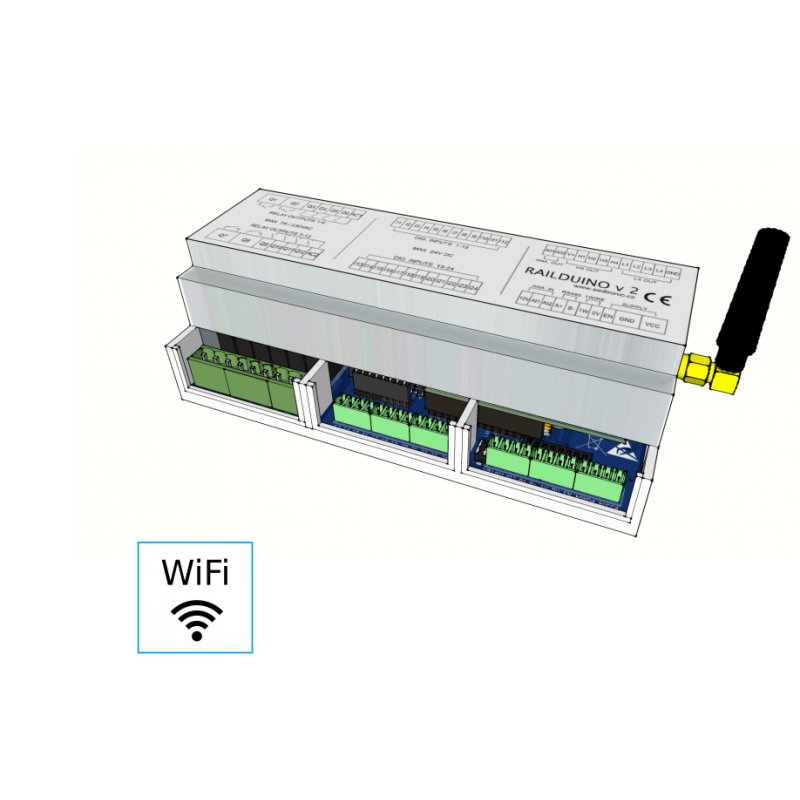
Railduino 2.1 - WiFi

CZK 6,799
VAT incl.

5619.01 VAT excl.

Input / Output module based on Arduino platform

24x digital inputs, 12x relay outputs, 8x digital outputs, 2x analog inputs, 2x analog outputs, 1-wire, WiFi connection ...

24DI.png 12RO.png 8DO.png 2AI.png 2AO.png wire.png 485.png LAN.png dip.png din.png LED.png

Relays type
Quantity
    On stock    2 pieces

Railduino module is a device working in connection with superior control system (e.g. Loxone) as so called distributed inputs / outputs. With this connection the control system is able to control external devices (e.g. lights, pumps etc.) using outputs or sense the values at the inputs of the module (e.g. buttons, contacts etc.). 

Module is equipped with both digital and analog inputs. There are also relay, digital and analog outputs - see the table below. Module can handle 1-wire devices 
(Maxim/Dallas) as favourite temperature sensors DS18B20 or DS2438 (Unica 1wire sens. module)

Inputs/outputs can be read/controlled by communication bus RS485 or by LAN within computer network. Both types of connections communicate using UDP protocol (User defined protocol). There can be connected up to 15 Railduino modules within the same network/bus.

Features and functions:

24x digital inputs - optically separated, max. input voltage 24V DC
12x relay outputs - galvanically separated, max. input current 7A/5A at 230V AC for 1 output
4x digital outputs High side switch - load current max 2A for 1 output, max 24V DC
4x digital outputs Low side switch - load current max 2A for 1 output, max 24V DC
2x analog inputs - input voltage 0 - 10V, resolution 1024 bitů
2x analog outputs - output voltage 0 - 10V 
1-wire bus - max. 10 pcs of sensors Dallas DS18B20, DS2438 (Unica 1wire sensor. modules)
RS485 bus - serial communication with superior control systems
USB - for reprogramming of the Arduino module
LAN - communication with computer network (only the module with this option!)
- status LEDs - indication and status of the module
DIP switch - module address settings, other function


Module settings - address and functions


Communication settings

 COMMUNICATION  DESCRIPTION  VALUE
 RS485  COMMUNICATION SPEED  115200 BD
 DATA BITS  8
 STOPBITS  1
 PARITY  NONE
 LAN  UDP INCOMING PORT  55555
 UDP OUTGOING PORT  44444
 MODBUS PORT  502
 IP ADDRESS DYNAMIC  IF DHCP SERVER IN LAN
 IP ADDRESS STATIC  192.168.150.15x - IF NO DHCP SERVER IN LAN (x is MODULE ADDRESS)


Status LED diodes

 LED DIODE  STATE  DESCRIPTION REMEDY
 BLUE  NOT LIT  MODULE BOOTING WAIT FOR 1 MINUTE
   MODULE AWAITING LAN CONNECTION CHECK THE LAN CONNECTION
 NO POWER SUPPLY CHECK THE POWER SUPPLY
 LIT  MODULE WITH STATIC IP CHECK DHCP SERVER
 BLINKS 1HZ  MODULE OPERATING -
 GREEN  NOT LIT  NO COMMUNICATION VIA LAN / RS485 -
 LIT  COMMUNICATING VIA LAN / RS485 -


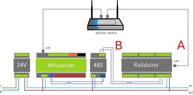
Connection to Loxone

A – LAN connection
B – RS485 bus connection

Both connections use UDP communication protocol (User defined protocol) or Modbus protocol (TCP or RTU) 


UDP communication settings in Loxone Config


LAN settings of communication for sensing inputs in Loxone Config:


LAN settings of communication for control of outputs in Loxone Config - address: "/dev/udp/255.255.255.255/44444"


RS485 settings of communication in Loxone Config:


MODBUS TCP communication settings in Loxone Config

Modbus mapa a adresování proměnných


Settings of Modbus TCP - insert Modbus server and set IP and port in Loxone Config:

Settings of Modbus TCP - set the address of the Modbus client - Railduino module

1. UDP protocol - Digital inputs


2. UDP protocol - Relay outputs


3. UDP protocol - Digital outputs - High side switch


4. UDP protocol - Digital outputs - Low side switch


5. UDP protocol - Analog inputs


6. UDP protocol - Analog outputs


7. UDP protocol - 1-wire bus


1. Modbus protocol - Digital inputs


2. Modbus protocol - Relay outputs


1. "What kind of connection to use with Loxone system?"

It depends what are you expecting: LAN connection is fast (delay in terms of microseconds) with immediate responses,
but there is need some workaround in LAN safety settings (subnets, VLANs etc..). RS485 is slower (delay in terms of
miliseconds), but is simple, safe and reliable.

2. "How long it will take from pushing the wall switch to actually switching on the lights?"

Whole procedure of communication from Railduino to Loxone and back can be described as follows:
1. Request processing by Railduino (pusching the button) and sending the satet to Loxone – in case of LAN max.
20ms, in case of RS485 max. 30ms
2. Processing in Loxone (reception of information and making of further steps) and sending command to
Railduino– in case of LAN max. 25ms, in case of RS485 max. 35ms
3. Processing in Railduino module (switching the lights on) ‐ in case of LAN max. 20ms, in case of RS485 max.
30ms
So the react time will be max. 95ms (in both cases of LAN or RS485).
Delay is minimum, longer delay will be created by powering up the current power source of LED lights.

3. "Is it possible to connect more then one Railduino to the same bus?"

Yes, every modul has its own address which is set using the DIP switch settings. It is possible to connect up to 15 modules
operating at the same bus LAN or RS485.

4. "How is the Railduino programmed with in Loxone Config? Does thy system detect inputs and outputs?"

It is neccessary to insert the virtual inputs and outputs into the Loxone program and make the correct settings (in case of
LAN connection). More details are in the Loxone example file which can be downloaded in the download section.

5. "What is the power consumption of Railduino module?"

In the worst scenario – Railduino module with LAN connection (24V power supply) has consumption of approx. 120mA
(with all relays off) and consumption of approx. 230mA (all relays on). Therefore power consumption is approx. 6W max.
Minimal consumption can be lower then 2W (no LAN and all relays off).

6. "Digital inputs are not working well, I have to push the switch two times, what is the problem?"

There is bad settings in the virtual input command settings ‐ Use as digital input must be UNchecked!
Railduino 2.1 manual - operating instructions EN ver. 10/14/2019 DOWNLOAD
Railduino 2.0 manual - operating instructions EN ver. 09/18/2019 DOWNLOAD
Railduino LED manual - operating instructions EN ver. 11/03/2020 DOWNLOAD
Template for Loxone Config CZ/EN ver. 12/30/2021 DOWNLOAD
Compiled firmware for Railduino modules last ver. 12/19/2024 DOWNLOAD
Uncompiled firmware for Railduino modules GITHUB DOWNLOAD
CE Declaration of conformity CZ/EN ver. 1/1/2018 DOWNLOAD


Reviews